Mobile Driving/Flying Cockpit with Motion and Tactile ( Build )

So far I'm not feeling like I'll need the HRS pedal face replacements. In fact I like that the brake pedal face is a bit narrower, but I won't discount that possibility in the future. I'm still liking how the pedal faces feel in general, but the smoother HRS throttle might be a small improvement.

Got my dead pedal dialed better today, probably the first time I've felt like it was exactly right. It is now perfectly comfortable and my foot rests there instinctively. I moved it further to the outer edge so there is no chance of catching my shoe on it if I'm sloppy with the clutch or if someone has really wide feet. There is a bit of an optical illusion here. The clutch pedal is far enough in front of the dead pedal that it will be able to slide over the top of it.

deadpedalbetterposition_8237.jpg
 
Last edited:
I couldn't resist bolting up the sliding plate template to see how it fit.

I added a bolt and washer in front of the clutch so I could actually try it out. Sure it's putting some pressure on the PLA, but there is a bunch of surface area with the beveled M6 bolts and 30mm of surface area under the quick releases. I'm only running 60kg of pressure for 100% brakes, so I guess we'll see if it holds up for a little while.

Plate_8243.jpg


I'll need to trim that small piece of 40x40 on the back to 85mm length.
Plate_8244.jpg


3 pedal operation

PLAPlateInstalled_8248.jpg


Left foot braking
PlateLeftFootBraking_8249.jpg
Under_8251.jpg
Back_8254.jpg


Notice that completely full 10 port USB hub ??? There is an overflow 7 port Hub on the right for my flight controls that I only plug in when I convert to flight mode.
lowerBack_8255.jpg
 
Last edited:
Yet another top notch idea. A sliding plate for brake and clutch is something I'd very much like to try.
Thanks! I've had this feature for a while with my Sprints even before they were inverted. I really like this a feature lot.

I even put out an STL file that people could use for a Sprint template to make their own.

Sprints_8256.jpg
 
Last edited:
Left to do to finish off.
  1. Fabricate Throttle plate and sliding clutch/brake plate. To your point about beveled bolts. I may bevel that back two holes above the short 40x40 piece. Partly for appearances, but mostly because I have a pile of SS M8x16 bevel bolts now and my M8x16 socket head bolts are running a bit thin.

  2. Trim short 40x40 piece supporting clutch pedal rear brackets to 85mm length.

  3. Add end caps to 40x40 pieces.

  4. Drill 40x40 x nearly 500mm piece running the length in back so it can bolt directly to the 40x120 and I can get rid of the ugly plate on top. ( Not a rush )
I have nothing against ordering a more SS M8x16 socket head bolts and I may need to. I was just very surprised that my fairly large M8x16 stock is nearly out.

I may neglect the UHMW tape under the plate since this is inverted and hangs down. It's not actually rubbing on the profile. Not only that but the underside of that 40x120 profile is FAR from pristine looking. Fortunately it's not in plan view.
 
Last edited:
The sliding plate template is rotated 180 degrees from the outline on the aluminum and I've changed another bolt hole since I took this picture. I did move a few M6 bolt holes a bit from the template. For the brake I moved the holes along the mount slots closer to the quick release clamps in back and centered the holes on the base slots in front a bit. It will have more range of motion fore/aft now. For the clutch I moved the holes 2mm wider and I centered the front holes on the pedal base slots so I might have more adjustability if I needed it. The Throttle holes were too narrow.

HE has drawings that show 68mm +-1 mm for all of the pedals. They have no drawings for their Smart Control. I thought I measured it well, but I should have used my hole punches and measured between the punch holes rather than eyeballing it to get the center hole dimensions faster for both the Smart Control holes and for the pedals.

I'll be drilling all holes 0.5mm oversize to help. ( 6.5mm and 8.5mm )
Tablesaw for the long straight cuts, then bandsaw for the smaller cuts, then belt sander to clean the edges, then drill press, random orbital sander, then 220 grit hand sand for final finish. Only the front rear edges will be visible, so no polish except around the front and rear edges.
MakePedalPlates_8259.jpg
 
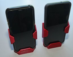
Mounted the pedal deck, put 40x40 end caps on, also shortened the 40x80 piece supporting my H-pattern shifter. Recently upgraded my Galaxy S8 to an S22 so I'm now printing a new phone holder that fits.

The U+ wiring is much cleaner looking and the quick releases have no issues hitting anything in back now. Now to catch my breath for a while and use my rig.

UltimateswithAluminumPlates_8265.jpg
UltimateswithAluminumPlates_8266.jpg
UltimateswithAluminumPlates_8267.jpg
 
I promised to test with and without the linear bearing to show whether it was necessary or helpful.
I think this 30 second video shows pretty conclusively what that answer is.

Stock Ultimate+ cushions pressing to about 60kg or so.

I tested the following:
1. Weak Spring ( Yellow )
2. Strong Spring ( Red )
3. Weak Spring with linear bearing support

I probably should have dropped the rig rather than have it up on casters when I did this. You can see the rig wobble a bit and that wouldn't normally happen.

You can also see that the Ultimate+ stock brake pedal cushions do offer a reasonable amount of travel. They have soft cushions that will increase travel by another 40% or so.

 
Last edited:
Reality again prevails; one could speculate that
linear bearings would similarly benefit isolated non-inverted pedals.
With the stock red springs and without the big inverted lever arm, I suspect it could make a difference, but the question is whether it would be enough to be worth the cost or if you would just adapt to having a bit more spring in your brakes. With the red springs inverted without the linear bearing it didn't feel as mushy and it may have bothered me more that I could see it moving than what I would feel in game.

What I didn't do is put on my VR headset and see how they felt in game. I believe the yellow springs would have racked and locked the M8 bolts on the bracket holes both making noise and cutting down on tactile while braking. The Red didn't move as far and may not reach that position.

So one could debate the value. The linear bearings are not inexpensive, but relative to everything else, maybe not so much.
 
An interesting question to answer would be, whether you felt the isolation drop, when being hard on the brakes. There might be tighter coupling to the rig, when there is pressure on the linear bearings.
 
An interesting question to answer would be, whether you felt the isolation drop, when being hard on the brakes. There might be tighter coupling to the rig, when there is pressure on the linear bearings.

There will absolutely be some drag, but given the forces involved from the transducers, I don't think this will be a problem. ( In practice I'm feeling a lot and I have plenty of extra power )

UHMW's coefficient of friction is 0.14 or lower. That is the material in the linear bearing. The surface area involved can effectively be factored out (in this application) because more surface area divides the force over a larger space lessening it proportionally.

Under full braking "for me" at 60kg there should be less than 8.4kg or 18.5 lbs of friction resisting vibration. That is my worst case scenario and I think the transducers are up for it.

Full throttle is considerably less than that.

Even if there is a little drop off, I would prefer to have accurate braking and have the tactile drop a bit under full braking. Before this modification, I would frequently lift my heel off the foot plate under heavy braking. My throttle foot would get something. This way I can actually feel the vibrations through the brake pedal if my wheels are sliding, or ABS is engaging.
 
Last edited:
My rig has likely reached a hardware plateau for a little while. Bumped out my phone holder by ~2mm to accommodate my new phone. No real excitement there.

I have some driving/racing and testing to do and I've got some videos planned. I also need to setup tactile for flight.

I think my rig has changed enough to warrant a full rig walkthrough and an updated conversion from driving to flight mode video.

I would like to create a few videos about tactile, however that is a potential can of worms. I don't want to create anything that looks or even smells like an advertisement and I don't want to present anything as the only solution. I'm thinking of presenting it like a journey in terms of where I started, and how I felt about things at different points. The key is not telling people to buy a pile of expensive hardware, but to explain my process and how my thoughts on this changed over time and why. Also emphasizing how strongly I felt about things that I've completely changed my mind about so as not to alienate people who have a different point of view.

I'm going to have to think about that a lot before starting it.
 

Attachments

  • NewPhoneMount_8268.jpg
    NewPhoneMount_8268.jpg
    149.4 KB · Views: 50
Last edited:
I wouldn't worry about it sounding like an ad or whatever you're concerned with. No one cares about watching walk through videos of budget setups. High end gear is what generates interest and helps people push their own builds to the next level. Go for it, I reckon.
 
I wouldn't worry about it sounding like an ad or whatever you're concerned with. No one cares about watching walk through videos of budget setups. High end gear is what generates interest and helps people push their own builds to the next level. Go for it, I reckon.
YouTube Title: "The Haptic Ferrari or NOT a budget Tactile system" :)
 
Last edited:

Latest News

Do you prefer licensed hardware?

  • Yes for me it is vital

  • Yes, but only if it's a manufacturer I like

  • Yes, but only if the price is right

  • No, a generic wheel is fine

  • No, I would be ok with a replica


Results are only viewable after voting.
Back
Top