HS6-GT – DIY H-Pattern Shifter

So... As I said before, this is almost a subjective theme. I have no experience with racing cars and with sport street cars. The only gear shift I have played in recent times, was a Mustang new Gen. And the engagement/disengagement was different. If I remember correctly, it was harder to disengage then to engage. And using logic, it makes more sense to make it harder to disengage then to engage. It will be worst to "pop out" by accident the gear out, then to make harder to engage.

I have as well some pics to make my argument:

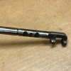
This are the shifter rod (or shaft), connected to the forks. Normally a gear box have 3 to 4 rods. One for a pair of gears. So, 1st and 2nd; 3rd and 4th; 5th and 6th. And normally they have notches were the Detent ball rolls on (not all gearboxes are equal...).

Mazda MX5 6 speed gearbox.
MAZDA_MX5_S62.jpg

Tremec gearbox from a Mustang (don´t know the version, but is not the latest model)
TREMEC_MUSTANG.jpg

And, the odd ball; JEEP gearbox
JEEP_SHIFT_ROD (2).jpg

Unfortunately is hard to find good pics about this subject. But, as you can see, all the notch are asymmetric and easier to engage and hard to disengage.

I have a really nice pdf from LUK company about detent balls. if you are interested to see, here it is:


This is why I designed the slops like this.

Hope this info is correct and helpful. And I would love to have more info about this subject. If any of you have something to share, please feel free!
 
Last edited:
I dont understand your concept, it is asymmetric in the "wrong way" for it to disengage easier, and very slight asymmetry between the lobes. I guess this is a better illustration of my idea of an asymmetric shape. You don't think this will change anything?

View attachment 454424

Is the distance traveled between the slopes limited to this distance? Increasing the gap between the "lobes" with a few millimeters would enable for a longer "slope" shape. But also introduce slightly more travel to the shifter. (If there is room for it...?)

I don't have the knowledge to modify this on my own yet. I might just use softer springs instead...
My last post, I only answer on question... Sorry.

The total travel of the shift lever ball, on the bottom, was defined by me as 12mm in one directions. So total 24mm from 3rd to 4th. This decision was made to avoid the lever to hit the shifter top plate. Avoiding then the metal hitting sound. And because the lever is bended around the exit hole of the shifter plate, was hard to make it the same distance from N to 3rd and N to 4th. This can be changed, by printing a new top plate (orange in the pic) with a bigger hole. But can be hard on the printed part to hold the return springs.
1615815823644.png


The same decision was made for the lateral movement. I define the lateral movement of the lever bottom ball as 10mm in one direction. so, 20mm in total. It can be made bigger, but I doubt it would make the shifter feel better.
 
having a problem with the sketch for arduino maybe someone can help me .Compilation terminated exit status 1 Joystick.h: no such file or directory .,..what do i do
 
Yes i understand. And your message got me thinking. There is this 3D hall sensors, like the one found in the shifter TH8A. Would be interesting to see if there is something similar to connect to the arduino.
Just fixing a strong magnet on the "Offset Lever" would be enough to generate some input information to the arduino, to play with.

I need to investigate about this.
Has anything changed? I am also thinking about making the h pattern with mlx90333 similar to th8a. MMjoy2 and arduino? Any help?
 
I never went far with this idea. I theory it works...

Watch this video. Almost in the final he talks about the "mlx90333". And isn't so positive remark. Althought if used in a shifter, his problem would be an issue.

More, i cannot help.
 
Thank you Thiago for this excellent project, and to anyone involved in testing and upgrading it. I didn't started my build yet, just because you've mentioned about new design- an old F1 style shifter. That's even more interesting, please share us any news on that one ;-)
 
Thank you Thiago for this excellent project, and to anyone involved in testing and upgrading it. I didn't started my build yet, just because you've mentioned about new design- an old F1 style shifter. That's even more interesting, please share us any news on that one ;-)
Hi! thank you for interest. But unfortunately I haven't spend time with a new version of the shifter or a new variant, like the Old F1/Old GT style.
Since I decided to return to sim racing in the last 5 months, I have updated my pedals and now I'm working in steering wheel variants. So, all shifters variants I have in my head went to second priority.
And, I don't believe I will have time for them in the near future... Sorry...
Tiago Viana
 
I completed the sketch and fixed the flickering LED. You can can download it here:

The updated STL for the Hall effect sensor holder is here:
https://drive.google.com/file/d/1yajACA6yQEs64r3aqhbsdQIl94EKXNiJ/view?usp=sharing

Note: Tiago has already added two recesses to hold the 5mm magnets on the selector, one either end. Note the comment in my previous post today about magnet polarity.

No support material is required for the hall sensor holder, but you will need to clean out one of the holes for each of the cable ties that hold the hall sensors in place. Print it in the orientation of the first image below.

Use the loops on the back edge of the holder for cable ties that aid cable management.

View attachment 421363

Use the holes on the underside for cable ties that hold the hall sensors in place. Thread the cable ties up from the bottom and then back down again so that close underneath the holder. Use small cable ties so the bulge with the cable tie latch will sit flush with the base of the holder, in each of the 3 square cut-outs.

View attachment 421364
Hi all,
I would like to ask for some help.
GSingle user made a Arduino sketch for the shifter with Hall Effect Sensor some time ago. The link for his Google drive is dead, now. And, unfortunately i never saved this sketch.
I tried to contact GSingle, but the last time he was active around here was in January 2021... (Hope everything ok with you mate!).
Anyone have the sketch saved around here?
Thanks in advance!

Tiago Viana
 
Last edited:
So... As I said before, this is almost a subjective theme. I have no experience with racing cars and with sport street cars. The only gear shift I have played in recent times, was a Mustang new Gen. And the engagement/disengagement was different. If I remember correctly, it was harder to disengage then to engage. And using logic, it makes more sense to make it harder to disengage then to engage. It will be worst to "pop out" by accident the gear out, then to make harder to engage.

I have as well some pics to make my argument:

This are the shifter rod (or shaft), connected to the forks. Normally a gear box have 3 to 4 rods. One for a pair of gears. So, 1st and 2nd; 3rd and 4th; 5th and 6th. And normally they have notches were the Detent ball rolls on (not all gearboxes are equal...).

Mazda MX5 6 speed gearbox.
View attachment 454612

Tremec gearbox from a Mustang (don´t know the version, but is not the latest model)
View attachment 454613

And, the odd ball; JEEP gearbox
View attachment 454611

Unfortunately is hard to find good pics about this subject. But, as you can see, all the notch are asymmetric and easier to engage and hard to disengage.

I have a really nice pdf from LUK company about detent balls. if you are interested to see, here it is:


This is why I designed the slops like this.

Hope this info is correct and helpful. And I would love to have more info about this subject. If any of you have something to share, please feel free!

This may be true, and all gearboxes feel differen. I mainly have experience from Japanese gearboxes. But are you taking in account that when engaging a gear you also have some resistance from the synchro rings and sleeves when engaging, but not when disengaging? :) Of course it takes a lot force to disengage a gear when the clutch is not pressed, but that is not how you change gear.

The problem as I see it, when you need unreasonable amount of force to disengage 4th gear to go to 5th gear, when 4th snaps out I have so much force applied to the stick that it snaps right into 3rd instead of 5th. This has never been an issue in a real car for me.
 
Last edited:
Hi Pasen.
I have one solution for the H pattern Slots (untested, of course...)
1643017655657.png


With a file (or dremel), you can remove material on the M6 Bolts (rosa color) and make a ramp shape, so that the M5 Spacer can slide better in the correct place. Other option, you can shave the M5 Spacer (Green color) in a ramp shape. Or both...
The only problem i see is the M5 Spacer can rotate. There is nothing to avoid a possible rotation... But, I believe this will not be a problem. The ramp hitting the bolt constantly, will avoid a wrong rotation. But this problem should be taken in consideration anyway.
Because this is an untested solution, how much material must you remove and shaving angle, is unknown...
As always, remove small quantities first. And go up till you find it is working for you.

Tiago
 
Hi Tiago,
Great to see you're still around here ;)
I'm still using your gearbox, and it's still going strong !
I had a few issues, mainly due to vibrations and unscrewing parts, but nothing broke so far.
And god knows i used it hard ... :D

But i've got a question for you !
I was trying to add a reverse button, and wanted to fiddle with the arduino sketch.
I downloaded the INO on the first page of the topic, version 1.2; i recognized nothing.
I went through all my old files, and found a version 1.2 from 2020; that's the one.

How are they so different, yet with the same ver ?
I don't know much about arduino, but that doesn't seems right :roflmao:

Quick look at the one i got laying around :

#include <Joystick.h>

Joystick_ Joystick(JOYSTICK_DEFAULT_REPORT_ID,
JOYSTICK_TYPE_JOYSTICK, 7, 0,
false, false, false, false, false, false,
false, false, false, false, false);

// Arduino Pin input Rename
const int G1 = 2;
const int G2 = 3;
const int G3 = 4;
const int G4 = 5;
const int G5 = 6;
const int G6 = 7;
const int REV = 8;

// Joystick Buttons (array of 7)
bool gearswitch[7]; // 7 variables, index counting 0 to 6 in the code

int lastgear = 0;


unsigned long time_rev = 0;
#define REVERSE_DURATION 1000 // you have this much time to engage reverse after 1st gear


void setup() {

// Initialize Button Pins
pinMode(G1, INPUT_PULLUP);
pinMode(G2, INPUT_PULLUP);
pinMode(G3, INPUT_PULLUP);
pinMode(G4, INPUT_PULLUP);
pinMode(G5, INPUT_PULLUP);
pinMode(G6, INPUT_PULLUP);
pinMode(REV, INPUT_PULLUP);

// Initialize Joystick Library
Joystick.begin();

}
 
Last edited:
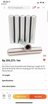
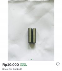
i was bought dowel pin od10x30mm and od8x30mm . I tried both and od8x30mm is better slide than od 10 if u use micro switch housing, But od8 used m5 20mm bolts but still strong. Btw, tell me what best spring for this shifter? i wanna try 0,6 x od 6mm x L 20mm spring.
 

Attachments

  • 9BABB8D1-A48C-4955-8A9B-93F226A5EA15.jpeg
    9BABB8D1-A48C-4955-8A9B-93F226A5EA15.jpeg
    161.5 KB · Views: 90
Last edited:
Hi Tiago,
Great to see you're still around here ;)
I'm still using your gearbox, and it's still going strong !
I had a few issues, mainly due to vibrations and unscrewing parts, but nothing broke so far.
And god knows i used it hard ... :D

But i've got a question for you !
I was trying to add a reverse button, and wanted to fiddle with the arduino sketch.
I downloaded the INO on the first page of the topic, version 1.2; i recognized nothing.
I went through all my old files, and found a version 1.2 from 2020; that's the one.

How are they so different, yet with the same ver ?
I don't know much about arduino, but that doesn't seems right :roflmao:

Quick look at the one i got laying around :

#include <Joystick.h>

Joystick_ Joystick(JOYSTICK_DEFAULT_REPORT_ID,
JOYSTICK_TYPE_JOYSTICK, 7, 0,
false, false, false, false, false, false,
false, false, false, false, false);

// Arduino Pin input Rename
const int G1 = 2;
const int G2 = 3;
const int G3 = 4;
const int G4 = 5;
const int G5 = 6;
const int G6 = 7;
const int REV = 8;

// Joystick Buttons (array of 7)
bool gearswitch[7]; // 7 variables, index counting 0 to 6 in the code

int lastgear = 0;


unsigned long time_rev = 0;
#define REVERSE_DURATION 1000 // you have this much time to engage reverse after 1st gear


void setup() {

// Initialize Button Pins
pinMode(G1, INPUT_PULLUP);
pinMode(G2, INPUT_PULLUP);
pinMode(G3, INPUT_PULLUP);
pinMode(G4, INPUT_PULLUP);
pinMode(G5, INPUT_PULLUP);
pinMode(G6, INPUT_PULLUP);
pinMode(REV, INPUT_PULLUP);

// Initialize Joystick Library
Joystick.begin();

}
Yes I remember this code to be the right one too. Is this code for the shifter with hall sensors or micro switches?
 
Hi all,

No idea... I have only the code version 1.1 and 1.2, and none are like that.

@pandax , can you share this sketch? Probably it is what me and @Fatapoc are looking for
Thanks in advance

Note: Nice to ear that the shifter is still working and going strong.
 

What do you think about subscription models in simracing?

  • It's fine

  • It's fine for hardware

  • It's fine for software

  • I don't like it

  • I don't like it for hardware

  • I don't like it for software

  • Other, please comment


Results are only viewable after voting.
Back
Top