DIY Sim / Productivity Rig with Tactile - Build Log

Hi All!

I am starting this log as a story of my journey in upgrading my outdated desk to proper sim rig. In the process I stumbled across a lot of issues and questions, for which I could not find detailed information and pictures (as far as I saw it is quite common for the subject). This I decided to write up a build log with all that was done.

First of all, here is what I started with:
image001.jpg

image003.jpg


This is my old gaming desk, which was used both for sim racing and work (I work home office). The biggest issue with it was that when I switched to Fanatec setup it was not adequate support any more and I had to start thing of something more stable. Also another issue was that every evening after finishing work I had to mount the wheel and handbrake to drive, then had to remove them in the morning. This is not so big deal, but some evening I was just too laze to do it so I wouldn't play.

First I started investigating buying pre-fabricated rig, but all of them wouldn't fit my needs. As I am long years experienced computer modder, of course decided to pursue the DIY path. Lucky for me I was able to source all materials locally and they were rather cheap - I was way under the pre-made rig prices.

First of all started by listing all the requirements:

1. Completely DIY scratch build by my design
2. Will be used both for work and sim racing
3. Seat has to be high so I can rest my feet on ground (as I am 1.90m tall this required seat height about 40-50cm above ground)
4. All driving gear should be mounted permanently and not get in the way of monitors while in work mode (Fanatec coming with QR system is great advantage)
5. Ideally pedals will be mounted so I can stretch my legs and rest on them while working
6. Integrated monitor stand is preferred
7. Shifter, handbrake should be mounted in such way that mouse can be used all the time in comfortable position (work mode)
8. Seat should have sliders to be comfortable for other people, also for easier access

Having this in mind, I went ahead and downloaded MayCad (apparently the preferred tool for designing with Alu extrusion profiles). Right now I do not have the original design at hand, but either way we will get to this stage later in the build log.

For now let's start with a Teaser picture of the current state of the rig:

image002.jpg


After building the first version, I could not stop so added the following:

1. Made new gear / info displays (I am using Simhub)
2. At some point switched to complete Fanatec setup (pedals and shifter)
3. Added a wind sim
4. Added 4 Aura bass shakers in chassis mode for tactile feedback
5. Added addressable RGB lighting showing REVs and light effects

Here is short video demoing the RGB lighting:


Of course I have other upgrades planned, but they will be done later on after the summer ends:

1. I have 4 more Dayton DAEX32EP-4 exciters, which will have to mount for additional effects - still have not decided where to put them exactly.
2. Will change monitor setup - actually already got whatever I need, but no time to install it - will be updated later when I get to it
3. Will have to upgrade my PC - I am still using Athlon FX 8350 with GeForce 1060 and it is getting very outdated
4. Will be retiring my modded PC case as it does not provide easy access. Already made preliminary design how all will look

In the upcoming days I will be posting replies on the topic with a lot of pictures and technical details following the extensive collection of photos I took in the process and also sharing all the technical solutions I came up.

Hope this helps others and you enjoy my story,
Cheers,
Stoyan
 
Last edited:

Part 31 - WRC Wheel With DIY Button Plate and Shifters​


Things at this point were getting rather interesting. I sold both my Driift wheel + CSL Hub and the WRC one, reason in next post. In the meantime I decided to build a wheel myself. Having a spare Metal QR I ordered the SRM Emulator Hub. Preferred the option to add funky switch and more buttons. I also ordered OMP rally wheel replica from Aliexpress:

IMG_7358.JPG


Net thing was to design nice button plate for it. Everything was hand drawn and i was really impatient. This is the reason I do not have any plans for it, which now when I look back was a mistake. Paper was stuck with double sided tape to Etalbond plate and a lot of manual work ensued:

IMG_7547.JPGIMG_7552.JPG

This is the result with carbon fiber vinyl:

IMG_7554.JPG


Testing with all buttons in place, looks good:

IMG_7561.JPG


Assembled with some Alu shifter paddles from Aliexpress and a 3d printed popular paddle shifter design (I know I have issues with the printer, took mi long months to clean them up, but still usable and acceptable:

IMG_7581.JPGIMG_7585.JPG

New wheel arrangement:

IMG_7597.JPG


I tested several paddle shifter designs, but was not satisfied neither with their strength nor feel. At the end I deiced to design my own paddle shifter. It is quite stable, strong feel, held up well for the 4 months I used it. Here it the result:

IMG_7864.JPGIMG_7869.JPG

Design will go on Thingiverse as well.
I prepared also a lot of video material on assembling it, but still did not get around to editing it.
 
Upvote 0

Part 32 - Fanatec Podium DD1​


All of these wheel sales and changes were done because I was planning switch to DD1. The WRC wheel is not supported, CSL hub is like toy and does not deserver metal QR1 :)

So at some point before new year the DD1 arrived. I used it for several days with Sim-Lab universal mount, but shortly the Podium Sim-Lab mount arrived. I should say the difference between the two mounts is incredible, the side mount adds so much in stiffness - never expected this. Also difference between CSW 2.5 and DD1 is night and day, should have purchased the DD in the beginning (good i managed to sell easy the CSW as well):

IMG_7591.JPG


First project was to design a KillSwitch with power button. All Aliexpress parts, came up nicely. Was painted with Tamiya model paints:

IMG_7652.JPGIMG_7678.JPG

An mounted on the Sim-Lab deck:

IMG_7686.JPGIMG_7687.JPG

Me trying to decide on color scheme:

IMG_7836.JPG


Here is how it looks now:

IMG_7971.JPGIMG_7992.JPGIMG_8628.JPG

Another close up WRC wheel:

IMG_7995.JPG


Thingiverse Paddle Shifters files will come HERE
 
Upvote 0

Part 33 - Custom Alu 8040/4040 Extrusion Profiles TV Rack​


By this time I had a lot of spare profiles and mounts laying around. Decided to replace my TV cupboard with something more compact. This is the base:

IMG_7910.JPG


Main structure looks like that:

IMG_7911.JPG


TV is VESA 200 mount, just used some angle brackets. Subwoofer was screwed to brackets underneath with wood screws:

IMG_7930.JPG


Some shelves from spare Etalbond shelving I had left from the rig, also tuning net. Big shelve is again Etalbond + matt vinyl sticker:

IMG_7939.JPGIMG_7952.JPG

Back and front completed setup:

IMG_7956.JPGIMG_7960.JPG

Shelves close-up:

IMG_8150.JPG


Also decided to modify my flower rack, now much smaller footprint:

IMG_8329.JPG


And the complete setup:

IMG_8910.JPG
 
Last edited:
Upvote 0

Part 34 - More Small Upgrades​


Finally invested in some racing shoes. These are Sparco fashion shoes, but still racing inspired. Have thin sole and round heel - very comfortable. Now I can feel much better the rumble motors, as well as grip and overall feel are greatly improved:

IMG_7723.JPG


The following picture has actually numerous upgrades: shifter mount was changed to shorter 8040 profile for rigidity. Mouse plate was separated from it mechanically, now less vibrations travel this way. Handbrake was ofsetted with 6mm alu washers, much better position relative to HE SQ. The 5x amp mount can be seen lower with its new position. Also all shakers were rewired and cables properly arranged. Aliexpress shifter knob added to the Fanatec shifter - it is very deep know and screws much lower than the original - no need of short shifter shaft. Testing new Dayton exciters, 25W if remember correctly. Somewhat good vibrations, but a lot of noise because of the plastic mounting plate - still not satisfied. New bike grip for HB handle (last one was too cheap - paper covered in silicon, which wore off fast) - feels great now. Length of Fanatec handbrake mechanism was adjusted, put Locktite this time - it was unscrewing constantly and needed readjustment. Since then have not touched it:


IMG_7990.JPG

New water bottle and beer holder position. Mouse pad mounting rearranged as described above - very stable, floating Etalbond plate is held only by one bolt on the side and is still without flex:

IMG_8205.JPG


As I am also using the video card for Bitcoin mining (it has to pay itself) I added Aliexpress backplate cooling solution. Temperatures are still the same, but backplate is definitely colder by touch:

IMG_8352.JPG


Made some fast mounts for my Saitek gaming keyboard - used mainly for menu navigation i Forza Horizon:

IMG_8505.JPG


Altogether now (gamepads have new place) very comfortable work place :

IMG_8364.JPG


New Drift wheel (again Aliexpress - love them) arrived. It was paired with a Podium hub - very good value as it comes with metal QR. Also buttons are needed for drifting, not sure even that i will ever add shifters on it. I was really worried as it has deeper dishing than the WRC wheel, also podium hub is about 15mm longer. Still it was in the correct place for drifting, at the end difference turned to be about 5-6 cm altogether:

IMG_8589.JPGIMG_8568.JPG

After new handbrake readjustment finally I managed to squeeze my Bride handle on the Heusinkveld SQ shifter. Yes, lost a little of the feel, but it is almost not noticeable, as the handle is all aluminum. Either way I have printed the new Dayton Puck holders I wrote earlier, now the vibration feel is great. The second Puck is still mounted to the Fanatec shifter side - both provide pretty solid feel - now both shifters feel much more alive. The relative placement shifter-handbrake handle now is great, I think this is the "final" position I will stick with:

IMG_8842.JPG


IMG_7997.JPG
 
Last edited:
Upvote 0
Great story, thanks for sharing.

Has it made you faster

Thanks! Of course it did not :)
It appears I am making it mainly because I enjoy it and building everything is as much hobby as using it. The sheer enjoinment and immersion is pretty amazing - how much you can achieve with the existing technology and DIY solutions. Sometimes I shutdown the platform, wind, vibrations and I realize how empty actually the whole experience looks without them.
Being engineer by trade and owning a 3D printer saves a lot of money and time - appears it is crucial component in the whole build.
 
Upvote 0

Part 35 - Carbon Skinning 3D printed Parts, Pt. 1​


I bought some Kevlar and Carbon Fiber fabric for other projects, but figured why not try it for this hobby as well. Obtained some resin and basecoat and started my first attmpt.

First of all I should say, in general it is possible to use only resin to glue to parts. I printed some paddle shifters and tried - failed miserably. After some attempts i got to a process, which works fairly satisfactory and is not complicated at all. There are a lot of videos on the topic and tutorials, so i will try sketching briefly only what i figured out in the process. I also shot videos of the whole process, but of course no time to edit them.

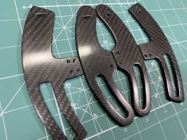
I spent some time enjoying the new WRC wheel, but never particularly liked the paddles. Downloaded a lot of options from Internet, printed them, still short of what I wanted. Then vectorized some myself and modified them to fit the size I wanted. At the end I accumulated quite of collection of paddles (some of them have carbon vinyl only to test how it goes - pretty satisfactory):

IMG_8510.JPG


I also at the time started designing a custom button box to replace my Saitec Keyboard, so naturally I printed some spare ones and attempted to carbon skin them. I found the best thickness for it is as follows:

Paddles are double sided carbon skinned, single layer of 240mg/cm carbon fabric - 3mm thickness of the 3D printed core
Button box face plate is single sided skinned with same fabric - 4mm thick

First step of the process is to sand them down to flat - provides much better adhesion. I did it with 240 grit sandpaper, dry and wet.
Then you mix the base coat according to its label. For mine it said to wait 1.5 hour before laying the first layer and it seemed correct. A lot of tutorials say 2 hours - tested it, did not work in my case. In general you can check stickiness with gloved finger - this is the best way to monitor and know when to proceed. These are the sanded parts with base layer on them:

IMG_8529.JPG


After 1 hour I usually start cutting the pieces of carbon cloth that I will be laying down. At 1.5 hour mark I start the process as follows - lay them flat on the table, stretch them lightly with gloves to straighten the pattern and lay them carefully on top of the part. Then with palms press gently to stick them together. For double sided just repeat on the side. If you placed thin layer of base coat and waited the correct amount of time you should be fine. This is the result:

IMG_8477.JPG


Till that stage I already made several attempts and had to restart the process. Now comes the next step, for which I did not find adequate information - vacuum bagging. I tried without it - results are quite unsatisfactory. The vacuum bags I use are standard one for keeping dry 3D printer filament. The level of vacuum you need is low - you should not overdo it. Food vacuum machines can be used, but it is a little too much. For me the easiest and cheapest method was with these bags. They are also reusable after the process. At this stage it tried both - using peel layer and wicking layer or without. After this attempt I realized that peel and wicking cloth are not needed now. They produces uneven and smudged fabric adhesion - you will see later in the pictures. Best result is achieved by just using a thing layer of Base Coat, waiting the correct amount of time, sticking the fabric and just vacuuming it. You should keep in mind that one side of the bag is smooth, but the back side is textured, so if you put more base coat it will leak on the outside of the carbon cloth. Here are the bagged parts:

IMG_8530.JPG


After waiting at least 8 hours, preferably overnight, next step comes - first resin layer. I saw in some tutorials the you can cut some of the fabric now. I tried it, was not happy - the edges become smudged, as the fabric is stuck only in the bottom - nothing holds the top layers.

What you do now is prepared the resin according to instructions and keep in mind this step requires a little more than the base coat and next resin layers - fabric is dry and will drink a lot of the resin. You want a smooth layer, laid not very fast so it has sometime to suck in. This layer is a little thicker and you would want to cover all parts well. After this is done you proceed with putting the peel layer fabric and on top the moisture wicking one - it will collect all the excess resin and provide you with surface with nice texture to which the next layers will adhere. When this is done you immediately vacuum bag them and leave them to dry at least 8 hours or preferably overnight. Here is how the parts look after putting the first resin layer before bagging them:

IMG_8535.JPG


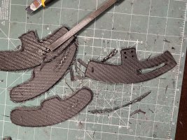
Next step can be done at your leisure - you can wait as much as you want between steps. After removing the peel and wicking layer you should be left with very rough but uniform surface. At this stage I found best to cut the excess fabric and open up all holes. The M3 mount holes on the shifters I realized are pretty hard to see now (them being double layered). On later projects I tried opening small holes with toothpick right after laying fist resin layer - worked like a treat. At this stage you should also lightly sand the surface - I used again 240 grit paper. If you reach black dust when sanding - STOP immediately - this is the carbon fiber. So after a lot of sanding and opening holes you should have something like this:

IMG_8551.JPGIMG_8555.JPG

For next steps timing is crucial - do not continue if you do not have the time to finish them. You can stop in the middle, but it will require then sanding and restarting the process. What you need here is to put the final 3-4 layers of resin, waiting between each for 2 hours. Resin has to dry for 2 hours to reach the perfect tack stage before next hand, ensuring proper bond between layers. I usually put 3 hands only, which takes roughly 4:15 hours.

After wash with water and clean with Isopropyl alcohol (this is something needed before basecoat as well) I mixed some resin and proceed with first layer. Here the rule is - more is lees. you should aim at putting uniform thin layers and build them up. You will need less resin at this stage - fabric is already thickened. You will most probably get spillage, but this is fixable - just more sanding. In general if you are gentle with the amount of resin and lay the parts flat on the table you should minimize it. On the other hand, shifters being double sided, I did not have this option so I had to sand a lot at the end. Here are the parts drying after first hand of resin:

IMG_8557.JPG


After waiting two hours you can proceed in same fashion with second layer. Then 2 hours wait - third layer. This is what my parts looked after laying the third hand of resin:

IMG_8563.JPGIMG_8564.JPG

Stay tuned for next post where sanding, clear coating and post processing will take place.
 
Upvote 0

Part 36 - Carbon Skinning 3D printed Parts, Pt. 2​


After the resin is completely dry we can proceed with sanding. Usually it take me more than 24 hours for full cure, so I wait about 2 days before proceeding. First I start wet sanding with 240 grit paper until I get total flat surface. Most of the sanding is done at this stage:

IMG_8624.JPG


After that it gets a little, I go with 400-600-800-1000 grit. The rightmost paddle is at 1000 grits:

IMG_8626.JPG


After sanding with 1000 I continued with scale model polishing paste:

IMG_8643.JPG


On the following picture you can see the difference between real fiber and vinyl sticker. The box plate does not look very good because it was the test where I put the peel and wicking layers after sticking with base coat. As it did not have flat surface pressing it the carbon threads on top bubbled up and remained high so after the resin they do not reflect properly light:

IMG_8646.JPG


As I already spent too much time on that decided to just proceed and use this plate. Still it is better than the vinyl, the resin surface gives it real carbon look. Test fitting the button box components:

IMG_8652.JPG


After going with all paddle all the way to the finishing polishing carbon really glossy look was achieved. As I was more after matt finish I sanded back to 1000 grit and started again. All was polished with coarse and fine compound. After it I sprayed with airbrush 3 layers of Mr Color GX Super Clear Flat top coat lacquer (GX 114), which you can also bur in spray cans. This is great top coat I use for scale modeling when I want to preserve more flat look on the paint. You should always put top coats after resin is polished to seal it and prevent it from yellowing with time. This is the end result with the flat clear coat:

IMG_8654.JPGIMG_8655.JPG

Some of the paddles came out great, some of them have the not-so-flat carbon cloth look. This was mainly due of me putting too much base coat, which went above the fabric when vacuumed:. Still looks better than the Aliexpress pre-made 3mm thick carbon plate.

IMG_8656.JPG


Using 3mm printed core with double sided skinning produced very sturdy item - there is zero flex in the paddles themselves. It being real carbon it feels and looks like it was made from full carbon plate. The button box is 4mm 3D printed base with single layer on top - still very stable stable item.

Pricewise - it is not expensive. The only expensive thing is the base coat and you cannot skip it, but once you buy it is enough for long time. Fabric itself is cheap, resin also, clear coats I have from before. Total spent in materials was:
240gr/m2 30x127cm carbon fabric - 9EUR
Base coat, black, 0.5kg - 44 EUR
Breather fabric 1x1.5m - 4.5 EUR
Peel ply 1x1.20m - 6EUR
Crystal Resin 0.7kg - 20 EUR


And this is the final product mounted on the WRC wheel:

IMG_8659.JPG


It came out more glossy than I wanted, but still not full gloss. It has the subtle flat look, but the combination of polishing + top coat seems not to be the best for my needs.

Now I am working on other carbon skinned items, most probably will try to sand them to 1000 or 2000 grit and them use Mr Colo Super Clear III - the gloss top coat I use for my car models. It produces very tough very clear finish, which polished looks amazing, this is regarded as the poor man's 3 component top coat. My plan is to preserve the flat finish I get at 1000-2000 and put gloss level layer on top, which will reflect the light properly and you will be able to see the twill. I somewhat tested it when washing the items after sanding - when they are wet light is reflected properly and it looks matt, but you can properly see the twill.
 
Upvote 0

Part 37 - Button Boxes​


At this stage I wanted to build a new button box which will substitute the Saitek Commander unit. I also bought on promotion some cool metallic 3D filament and wanted to try it out. The most important part of the controller was to have directional pad and big start button mapped to enter for menu navigation. Also it would double as wind sim controller and will provide the 12V power line to it. I decided to throw in some toggle switches which will cut the power for the fans. The directional switch was easily made with some push buttons soldered to a piece or project board. The pad itself i found on Thingiverse and deigned a housing for it:

IMG_8404.JPGIMG_8406.JPG

I also wanted to build a new display box, which would resemble the time piece you can find in Audi Quattro S1/S2 rally car (right on the screenshot below):

IMG_8841.JPG


The time box has 4 push buttons and two rotary encoders. It is also driving my aRGB lights and the speed display. The other button box was just filled in with some button, which were arranged to maximize space use:

IMG_8571.JPG


The display box was painted in Gunmetal by Zero Colors, clear coated with the Flat lacquer. Top button is connected on the Reset pin:

IMG_8705.JPGIMG_8706.JPG

Then I made some custom stickers for the box and steering wheel:

IMG_8731.JPGIMG_8732.JPG

The two new boxes mounted:

IMG_8840.JPG


And the complete setup (another custom box was made for the 16x2 LCD):

IMG_8802.JPG
 
Upvote 0

Part 38 - Button Boxes, continued​


This is more of a list for the new designs I am playing with.
First off I bought a car kill switch and reworked it with a 3D printed part and some cutting to have much smaller footprint:

IMG_8938.JPG


Made a quick box holding a single rotary encoder, which connects to the display box with 9 pin cable. On its side it connects next to the speed display:

IMG_9093.JPGIMG_9100.JPG

Here is a picture of the complete setup:

IMG_9111.JPG


You can see in the corner small box. This is second control box to use for navigation, which was placed between mouse pad and shifter. It has a Funky Alps switch (7 functions), two buttons and a toggle switch. All buttons, directions on Alps encoder, were connected in matrix layout 7x2. Toggle switch is used to select the matrix row in use, thus making possible all buttons and Alps directions to have double function. Alps encoder is mapped to keyboard arrows and enter when pressed, bottom button is ESC, upper one is for additional features. When circuit is switched it is used for ingame seat adjustment. Rotary functions on the Funky switch also work. The Arduino that controls it is also used to power my central Wind Sim fan and the 16x2 display:

IMG_9147.JPGIMG_9121.JPG

IMG_9148.JPG


Made a new custom enclosure for the speed display, tested out the new carbon fiber high quality vinyl I bought recently:

IMG_9116.JPG


I also started working on several new boxes, which I would like eventually to build into a car look-a-like central console somewhere on the side of the handbrake:

IMG_9139.JPGIMG_9159.JPG
 
Upvote 0

Part 39 - Central Fan for Wind Sim​


Around this time the new SimHub version came out. It featured reworked design for the WindSim controls, which now has its own menu section. As there you have Left, Right and Center channels, I decided why not to add third one to the setup.

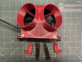
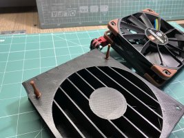
At first I wanted to put something slim and not really visible, but the printed started acting on me and could not print the original design (it was too long print, also featuring very long bridges). After several days with multiple failed attempts, I decided to try also another option. I purchased some car vents and build 120mm fan splitter for the tubes. I was sure I will not like the design, but anyhow attempted it (reasons below):

IMG_8813.JPGIMG_8827.JPG

Printed a lot of GoPro mounts and here it is:
IMG_8847.JPGIMG_8850.JPG

As I expected, this design had lot of issues, as follows:
- Takes up too much space and cannot see computer any more, which is the center piece of the rig
- It is noisy, like, really noisy. The pipes introduce great echo and at full speed the Noctua Industrial fan crates quite unpleasant noise
- Lag. I was expecting it, but not that much. The difference between side fans, which are direct and the center vents was enormous. When this fan speeds up the wind delivered come like a second later than the side ones. Also this long air way introduces very slow build up and down of the wind itself - the side fans provide much more direct feeling when you change speed or direction.

I went with the design, as I wanted to see if it is feasible to use it in single fan installation, which it does. At the end it delivers strong wind and uses only one fan, it is compact solution on the whole:

IMG_8836.JPG


At some point the printer decided to behave, so I managed to continue with my original custom design. All the failed prints before at least allowed me to test and correct all mistakes and cleanup the final design. So here is what I got:

IMG_8915.JPGIMG_8917.JPG

it is a blower type shroud, which is only 3cm tall if I remember correctly. It has build in somewhat wind tunnel and fins to minimize backpressure. I wanted it to be in the middle of monitor and resemble the airvents you have on the roofs of rally cars. In my opinion it simulates pretty well the airflow, which I would expect from such vents. Also it is similar to the sunroof I had on a previous car I owned. The delivered wind is pretty strong, noise is same as side fans. For me this is the perfect design I needed, I guess will stick with it. All three fans now operate at 90% as they are very powerful and all three have wind tunnels which really produces quire a draft. Friends coming over to play say it is too powerful for them, but I like it:

IMG_8927.JPGIMG_8928.JPG

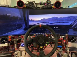
this is how it looks from driver's perspective - pretty neat:

IMG_8932.JPG


At 40% these fans produce very nice breeze, which will be welcome in the not so hot summer days when I do not want to use air-conditioning.
 
Upvote 0

Part 40 - Heusinkveld Ultimate+, Handbrake, F1 Esports V2 Wheel​


I am not big fan of the F1 series, but 2021 was on big promotion, so I tried it - not bad. Little strange with GT style cockpit, but that's it. I was wondering for some time if I wanted to buy the new F1 Esports wheel, so this was good excuse to finally do it. I was curious how the smaller diameter will work with the DD1 - have to say after dialing in the settings it is really great! I pretty much like the smooth feel of the Alcantara handles, very nice touch, much better than the OMP replica suede. also the open on the bottom wheel design really fits well, as my arms are relatively large and I was worried it will not be comfortable. Another reason to buy it was the great value - in the price I have the magnetic paddles and the metal QR. I was really curious to test the paddles - the ones I designed already feel pretty good, better than the WRC wheel magnetic mod I made earlier, but still being 3D printed in PLA you can feel some overall softness in the construction. If I cut them from metal or carbon fiber it will be much better, but too expensive and complicated mod. So long story short, the Fanatec magnetic shifters really feel great. Have much better feel than the McLaren shifter. Compared to my design they also are way better.

So now again wheels were rearranged:

IMG_9244.JPG


I was planning NOT to change my pedals any time soon, but got an offer to sell them, so could not resist. I was considering HE Sprints for some time now. Having Inverted V3s with both dampers and really liking how they work I was wondering long time will I miss them. Several times I tried removing damping to remember how it feels - yes, in braking I don't feel big difference as it is with the upgrade kit, but the throttle just seemed lame to me. Really like the dampening at 1.2-1.5 setting, otherwise the pedal is just too light for my liking. Having all these thoughts, together with the idea that I would like to see bigger upgrade when I am changing the V3 and investing already a significant amount of money (I was considering the redline edition Sprits), decided to go with Ultimate+. Another option was to buy Ultimates, as right now they have very food promotion from Heusinkveld and later adding the ultimate+ upgrade kit, but what the hell, this is long term investment, which I will always wonder if I am missing on something - went the full way.

I am big fan of inverted pedals, so ordered the new Sim-Lab inverted pedal mount. Looks like great piece of kit. Everything was fast dismounted and side plates were quickly put in place:

IMG_9267.JPG


Big question now was how to mount all the Bass Shakers. I had some 100mm profiles, which were mounted as pictured below on the pedal rails. One Aura bass shaker was then screwed directly on to them with M6 mounts. This will be my engine/jump landing shaker. Controller box was also mounted on top:

IMG_9278.JPG


On the other side the Heusinkveld Ultimate+ pedal were mounted - nothing special:

IMG_9277.JPG


Then the whole construction was dropped into place. As my rig is a little different than Sim-Lab ones, I had 20mm of difference between side rails that had to be accounted for. Me being well prepared always and Sim-Labs having great documentation, I asked a friend to produce for me 6 alu milled washers, 10mm height, 20mm diameter with M8 bore. I also ordered longer bolts, but on all pictures and designs I saw they looked flat headed. Turns out the side plates are made for countersunk bolt, thus the ugly big washers. I put everything as it should be so when the correct bolts arrive I will be able to exchange them quickly:

IMG_9280.JPG


I also had ordered some longer 4040 profiles to go under the pedal plate, 20 mm longer than the original ones. They will carry the pedal plate, will be separated mechanically by rubber washers to minimize vibration travel throughout the rig:

IMG_9288.JPG


Now question was how to actually mount the two Auras, which simulate wheel effects. I reused some of the 100mm extrusions I had before for the same purpose and this is how the mount points looked (shakers will be facing down when mounted):

IMG_9287.JPG


What was left was to mount the pedal plate:

IMG_9292.JPG


Have to say the Sim-Lab Inverted Pedal mount is great! The whole construction is very stiff now, much more than with the V3s. Ease of installation and maintenance is much better now - totally worth it. Also as it goes for looks - it really goes great with the HE pedals. Also the freedom for adjustment is immense - really great product.

Same should be said about the HE Ultimate+ pedals. I had to readjust the throttle pedal after initial testing - took me a minute to achieve the comfortable position I wanted. The pedals are really impressive, very clean look, much less parts than the V3 and the constant oiling-squeaking now is gone.

Side view of the whole thing - bass shaker placement is clearly visible from this angle:

IMG_9294.JPG


Mounted like this the top bass shaker of course propagates effects throughout the chassis, but going through the side plates they are dampened a lot. Generally good position, do not think I will have to do something about it. Wish I could say the same for the bottom ones - still plagued by an issue I had before - all vibrations from both bottom shakers can be felt through the whole chassis and are pretty strong. I know what is the reason, but too much effort to fix and still will not be totally gone. The only solion I see at the moment is to change the dampers with smaller ones, which have bolts on both side. I believe this will finally start really dampening the construction.

Another change is the new handbrake. I really did not have any time to figure out proper mounting, so I just slapped it on the side wheel struts. It works, but it is far from reach - will be dealt with some day when I have time:

IMG_9290.JPG


I had only one night to test the new setup, as I am away from the rig once again for some time. I spent only short hour playing and have to say the difference is impressive. The pedal deck is very stiff, I could not notice any flex. It totally can withstand the full 140kg force, promised by the pedal load cell. On the other hand, this being a GT upright type of rig, it is very hard to actually deliver this amount of force.

I tested mainly in Dirt Rally 2.0 - have to say immediately I got used to the new pedals and handbrake and had far superior control and modulation for both in the default settings. Still it remains to be seen when I start playing with adjustment, but have to say the upgrade was totally worth it and the level of immersion was boosted big time.

I am still wondering about the throttle - it was somewhat strange to have it floor mounted, but got used to it. For the time being I really like it dropped, but it is possible it try to bottom mount it at some point.
 
Upvote 0

Part 39 - Central Fan for Wind Sim​


Around this time the new SimHub version came out. It featured reworked design for the WindSim controls, which now has its own menu section. As there you have Left, Right and Center channels, I decided why not to add third one to the setup.

At first I wanted to put something slim and not really visible, but the printed started acting on me and could not print the original design (it was too long print, also featuring very long bridges). After several days with multiple failed attempts, I decided to try also another option. I purchased some car vents and build 120mm fan splitter for the tubes. I was sure I will not like the design, but anyhow attempted it (reasons below):

View attachment 559440View attachment 559441

Printed a lot of GoPro mounts and here it is:
View attachment 559443View attachment 559444

As I expected, this design had lot of issues, as follows:
- Takes up too much space and cannot see computer any more, which is the center piece of the rig
- It is noisy, like, really noisy. The pipes introduce great echo and at full speed the Noctua Industrial fan crates quite unpleasant noise
- Lag. I was expecting it, but not that much. The difference between side fans, which are direct and the center vents was enormous. When this fan speeds up the wind delivered come like a second later than the side ones. Also this long air way introduces very slow build up and down of the wind itself - the side fans provide much more direct feeling when you change speed or direction.

I went with the design, as I wanted to see if it is feasible to use it in single fan installation, which it does. At the end it delivers strong wind and uses only one fan, it is compact solution on the whole:

View attachment 559442

At some point the printer decided to behave, so I managed to continue with my original custom design. All the failed prints before at least allowed me to test and correct all mistakes and cleanup the final design. So here is what I got:

View attachment 559445View attachment 559446

it is a blower type shroud, which is only 3cm tall if I remember correctly. It has build in somewhat wind tunnel and fins to minimize backpressure. I wanted it to be in the middle of monitor and resemble the airvents you have on the roofs of rally cars. In my opinion it simulates pretty well the airflow, which I would expect from such vents. Also it is similar to the sunroof I had on a previous car I owned. The delivered wind is pretty strong, noise is same as side fans. For me this is the perfect design I needed, I guess will stick with it. All three fans now operate at 90% as they are very powerful and all three have wind tunnels which really produces quire a draft. Friends coming over to play say it is too powerful for them, but I like it:

View attachment 559447View attachment 559448

this is how it looks from driver's perspective - pretty neat:

View attachment 559449

At 40% these fans produce very nice breeze, which will be welcome in the not so hot summer days when I do not want to use air-conditioning.
Thank you for posting your trial and error as well as your successes! I am definitely interested in adding wind to my rig.
 
Upvote 0
robot servos are not the best choice around for belt tensioner as it is noisy
My understanding is that stepper motor harness tensioners are also noisy.
An advantage of robot servo brackets is that they allow installing
with harness webbing on both sides,
so not directly bolted to any structure that increases noise coupling.

A direct drive harness tensioner could be simpler and more ideal,
since PWM control of simple DC motors directly affects torque,
which is all that is wanted.
I do not know how to guestimate stall torque for cheap DC motors
and would prefer to avoid gearboxes, because of noise.

6x super capacitors
I hope those are NOT just bare supercaps, but instead include voltage leveling.
That is why I got an assembly nominally intended for automotive use
and cut it in half.
I do not bother trying to quickly discharge supercaps when not in use;
8 Volts is not very dangerous, and mine eventually discharge after an hour or so.

I like my green harness, but like your purple more...
 
Last edited:
Upvote 0
My understanding is that stepper motor harness tensioners are also noisy.

Based on what I see on videos and read online - my guess exactly. Either way noise does not bother me that much, I am willing to accept it - after all the system is cheap, works very well - do not see any reason to go for commercial one. My only regret is that I did not read through all information available online and first bought the 35kg version - should have gone for 65kg right away.

On the other hand, I will attempt to build Wotever's system - already ordered all parts. Have a feeling this was not wise investment, but am very curious to see how it works myself. Also really want to test the SimHub plugin that drives the tensioners - ultimately would like to have the same driving also hobby servos. Me not being very good in programming I prefer to use system that is being developed and upgraded with future support. When I build it will make more in-depth comparison and after that will be selling one of the systems most probably.

I hope those are NOT just bare supercaps, but instead include voltage leveling.

Nope, they are not. I was following your documentation and did everything the same way, thanks for putting all the information together :) I also bought the set of 6 pre soldered with balance circuits and cut them in half.

The discharge circuit is only a proof of concept, I added it simply because it was very quick mod and I wanted to see how it will work. Ultimately I will build another circuit with a relay which will switch between offload and PSU circuit automatically when I cut accessories power. The circuit will use a big resistor for offload and only an indicator lamp. The latest button boxes I showed in latest posts have this designed in them.

I like my green harness, but like your purple more...

I was going for TAKATA green replica, but have nothing green on the rig. When I saw the purple ones couldn't help but order them. Also them being cheap Chinese replica they are very cheap - about 50EUR for 5-point version. Really did not want red or blue belts, black is boring, but the purple ones really fit in the color scheme. I have them for 4 months now, they are much better quality than I expected. The only issue I have is one of the buckle clips is sticking a little and does not allow the belt to clip in easily - have to open and clean them some day.
 
Upvote 0
Also really want to test the SimHub plugin that drives the tensioners - ultimately would like to have the same driving also hobby servos.
On SimHub discord's #experimental-belt discussion channel,
@Beano iRacing also expressed interest in using servos (04/13/2022).
Early (05/2021) versions of @Wotever's system
used a Custom Serial profile and Arduino sketch
that were fairly easy to understand.
Some of that protocol involved stepper motor speed changes,
which would not translate to hobby servos.
I could have hacked my servo sketch to use his plugin,
but that serial protocol seemed excessively verbose,
where the intent is to eventually control multiple devices
(MIDI for tactile, shifter, button box, speed fans, tensioners and G seat)
using only one or two USB modules, one at seatback and another on wheel stand.
Consequently, our protocol evolved to a degenerate (mostly 2 character) version of MIDI.

Since USB automagically handles byte synchronization,
single-byte commands are more robust and simpler to implement,
but Custom Serial's 7-bit ASCII limitation severely constrains possibilities.
 
Upvote 0
On SimHub discord's #experimental-belt discussion channel,
@Beano iRacing also expressed interest in using servos (04/13/2022).
Early (05/2021) versions of @Wotever's system
used a Custom Serial profile and Arduino sketch
that were fairly easy to understand.
Some of that protocol involved stepper motor speed changes,
which would not translate to hobby servos.
I could have hacked my servo sketch to use his plugin,
but that serial protocol seemed excessively verbose,
where the intent is to eventually control multiple devices
(MIDI for tactile, shifter, button box, speed fans, tensioners and G seat)
using only one or two USB modules, one at seatback and another on wheel stand.
Consequently, our protocol evolved to a degenerate (mostly 2 character) version of MIDI.

Since USB automagically handles byte synchronization,
single-byte commands are more robust and simpler to implement,
but Custom Serial's 7-bit ASCII limitation severely constrains possibilities.
I am not sure if I understand correctly your post...

What is the goal of your work?
Is it intended to replace the Arduino sketch of the Simhub belt tensioner from Wotever?
 
Upvote 0
replace the Arduino sketch of the Simhub belt tensioner
Yes, I was responding to @StuyoDGr8's interest in using SimHub's plugin
to drive servos instead of steppers. This involves more than replacing
one Arduino library with another, but not a ton more.
Since the SimHub plugin evolved from this earlier implementation,
reverse-engineering is less daunting...
 
Upvote 0

Part 41 - Heusinkveld Handbrake and Sequential Shifter Mount, NLR Motion Platform​


As the handbrake was in the wrong place I managed fabricate relatively simple way of mounting it next to the SQ shifter using a 100mm extrusion and angle bracket:

E83BD4BA-9360-4070-B4F8-527A79BF8370.jpeg95A02E13-292F-4E90-9F15-3856B42EA9F5.jpeg

And this is how it sits:

C06EBAC6-3B08-46E4-9E67-EF3A6F6E0B2B.jpegD40A43E6-FB6E-4D73-A023-62A879DFAB1B.jpeg

Much more comfortable now, also a lot cleaner:

C1FECFAE-2B80-406D-8D61-8FD51BDB9AB2.jpeg931F4CD2-959B-4AD0-9FA9-47C4296FE58B.jpeg

While I was away a big pile of boxes arrived yet again:
80A67B65-27F2-4290-A103-B5800716F2C5.jpeg


The most important box was the new Next Level Racing Motion Plus platform. The biggest question I had last weeks is how much travel it has exactly, as I could not find anything that states it. Of course first thing to do is measure it

Fully extended:

55666891-7619-47D5-84D1-E7FB1CE58565.jpeg


Fully compressed:

F4439D10-1211-4EBD-A514-2D668F179BCA.jpeg


Parked state:

5DBC6CD1-4584-4B8C-90EC-59DF3D151384.jpeg


So final measurements were: 150-115-120mm

I made a short video showing the power cycle with measurements:

 
Last edited:
Upvote 0

Part 42 - NLR Motion Plus Platform DiY Sim Rig Installation​


My rig being custom DIY it does not have almost any spacings compatible with commercial rigs, so again I had to come up with mounting solution for the Next Level Motion Plus Platform. Basically I went the same way as with the V3 seat mover - the plan is to put additional layer of longitudal 4040 profiles, which will hold the platform below the rig.

The sway bar also was challenging - its outer mount holes were exactly at the end of the back cross 8040 bar. I had to mount something longer below to accommodate the correct spacing. This was relatively easy as I had either way to put the additional 40mm layer, so i reused the side struts, which were not needed any more after I dropped the V3 in:

14126C2B-B43C-47C4-BD76-8D7160F3F498.jpeg


This is how the sway bar mounts below the rig now:

EB744065-BB78-4F02-B857-9E82954C31BE.jpeg


No, I have not punctured a tire. As there was no other help around I had to rely on my trusted low profile hydraulic jack to do the job. It worked perfectly install was very easy one person job with it:

E6919FE0-D690-46E3-AAD7-DD5109DD388F.jpeg


I also had to do some reconfiguration of the shaker/pedal plate structure to accommodate the new changes. Also am almost out of profiles, so had to improvise:

D305A4F1-6DC0-4436-9521-BA64DCA6DB34.jpeg


Next the platform was assembled and the side mounting extrusions were placed:

A08A6A70-C386-4FAB-9640-66EBC3DA420A.jpeg


Removed the cross bars that were holding my pedal plate, pre-assembled everything together to be ready to drop in the rig:

C8D276C4-6DB6-4D88-AE68-BB285E65FFEC.jpeg


Test fitting the bass shaker assembly:

5ABCF7F6-8E1E-46BE-8EB8-56BC7B9379C1.jpeg


And this is how it is supposed to go with the pedal plate attached:

F974F40C-4415-4AF8-BFD7-C4B167980743.jpegC7266F88-BCA3-4271-9E3D-E855AE2E7102.jpeg
F2744065-5DB3-4AFB-9D77-5672966683DB.jpeg


Looks ok for the time being, if I see any issues with spacing will just add longer profiles and move the shakers further in-front. Also I am still considering maybe to put them vertically to test how vibrations will feel in the heel plate.
 
Last edited:
Upvote 0
Back
Top