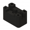
HS6-GT – DIY H-Pattern Shifter

As I already stated, I'm no expert in arduino and programming, so I can be wrong.
I understand what a teensy Lc is, but I cannot see a big advantage for this application. In the end we just need to send a push button function to the PC. We will not need high bit rate communication, big RAM, etc.
And the price of one teensy Lc, is around 20€. I can get 3 arduino pro micro for around 6€! It is hard to beat this price difference! And for our needs, the arduino is good enough! We just need a good instalation manual.

I'm expecting to be able to connect only 4 Hall effect sensor and make the 6 gates position, but if doesn't go as expected, I can use 6 HES to simulate the gates, and the arduino pro micro has 10 analog points, so it is enough!
Arduino for the win! ;)

Tiago Viana


Hey Bitacaia,
You can buy teensy LC´s for around 11€ if you search the web.
In China they might be even cheaper.

I mentioned it because it comes with a joystick library. In my oppinion it makes it easier to use and it supports up to 32 buttons, 6 axis and one hat switch. It´s super easy to use and i can fully recommend it as a base for DIY controllers.

It will be interesting where H-Shifters might come some day. Nowadays it´s just buttons, that´s correct. But one day you might be able to use analog inputs in H-Shifters to really simulate also shifter travel or something, to create feedback for example.
H-Shifters are still very simple, so a lot of potential for evolution.

I didn't design the shifter thinking about this extra feedback (clutch Engagement .eg). But it is a flexible design, since it is using printed parts.

There is some people already playing with this idea (clutch engagement).

This is servo actuated locking mech.

Bowden tube connected with the clutch (I love the shifter mech from this guy, complex and ugly, but amazing!!!)

And in the iRacing forum i saw once a H-Shifter with electromagnets actuators to locking the shifter.

I´m always for the most easy and reliable solution (and cheaper), so I believe the bowden tube connected to the clutch pedal would be this solution. On the shifter side, it would only require a mechanism to lock the longitudinal movement of the shifer lever. I believe it can be easy to make this.
Unfortunately this is not in my priority list, and i´m not a big fan of this.


There is so much reality you can implement, but at what cost? Can we profit much more with it?

Tiago Viana
 
Last edited:
Well evolution is a wonderful thing. There must be someone to start things and try them out.
If nobody would do it, there would be no progression and we would still travel by horse.

At first cost is always high when going a new route. But in the end it might be the next step.
(Look at DD-Wheels or loadcell Brakes)
H-Shifters especially have so much potential...but i get your point.
Your design is clever and low cost. No question about that. Once it is finished there is the possibility of the next step.
 
I have nothing technical to add to your post but, want to say I appreciate all the discussion going on, as an "older" sim racer who is being left behind with all the new technology happening so fast it is very educational to me at least to follow along and try and learn something new!

Last year I built my own hydraulic/pot based pedals, been looking at DD wheels and have been trying to figure out my direction for a shifter. I'm replacing the G27 setup I have been using for the past 10 yrs. I currently do not own a 3D printer but have looked into them. This thread has been a real inspiration thanks to all who are sharing ideas/discussion!
 
I didn't design the shifter thinking about this extra feedback (clutch Engagement .eg). But it is a flexible design, since it is using printed parts.

There is some people already playing with this idea (clutch engagement).

This is servo actuated locking mech.

Bowden tube connected with the clutch (I love the shifter mech from this guy, complex and ugly, but amazing!!!)

And in the iRacing forum i saw once a H-Shifter with electromagnets actuators to locking the shifter.

I´m always for the most easy and reliable solution (and cheaper), so I believe the bowden tube connected to the clutch pedal would be this solution. On the shifter side, it would only require a mechanism to lock the longitudinal movement of the shifer lever. I believe it can be easy to make this.
Unfortunately this is not in my priority list, and i´m not a big fan of this.


There is so much reality you can implement, but at what cost? Can we profit much more with it?

Tiago Viana
I saw the second video some time ago and I didn't like it much, but the first is new to me and I think it's very well done. I like how it seems to behave.
 
It will be interesting where H-Shifters might come some day. Nowadays it´s just buttons, that´s correct. But one day you might be able to use analog inputs in H-Shifters to really simulate also shifter travel or something, to create feedback for example.
The Logitech shifter is analog. Even though there are physical gates to shift into, they merely took a joystick's X-Y potentiometers and mapped them in software to the gears. Doesn't hold up over time as the pots wear, but it was an ingenious approach.
 
Well evolution is a wonderful thing. There must be someone to start things and try them out.
If nobody would do it, there would be no progression and we would still travel by horse.

At first cost is always high when going a new route. But in the end it might be the next step.
(Look at DD-Wheels or loadcell Brakes)
H-Shifters especially have so much potential...but i get your point.
Your design is clever and low cost. No question about that. Once it is finished there is the possibility of the next step.
Don´t get me wrong, evolution is very important. But I have more fun designing something cheap than something expensive. I could design a shifter with laser cutted sheet metal parts, like Heusinkveld parts. It would cost me allot of money, but i wouldn't have the fun of sharing something with the community.

In my opinion the shifter isnt as usefull for driving fast and consistent as some good pedals and a good wheel. I would invest first on pedals, then in the wheel (never forget the rig) and just in the end, the shifter. For the immersion a good shifter is important, but not to make you faster. (people in the end prefer to drive faster, for sure)

I have nothing technical to add to your post but, want to say I appreciate all the discussion going on, as an "older" sim racer who is being left behind with all the new technology happening so fast it is very educational to me at least to follow along and try and learn something new!

Last year I built my own hydraulic/pot based pedals, been looking at DD wheels and have been trying to figure out my direction for a shifter. I'm replacing the G27 setup I have been using for the past 10 yrs. I currently do not own a 3D printer but have looked into them. This thread has been a real inspiration thanks to all who are sharing ideas/discussion!

Not having a 3d printer isn't a problem, for sure you can ask someone to print the parts for you.
In this Reddit page, you can ask them to print.

For sure there is other alternatives. If someone knows more, please share with us.
And if you can make your own pedals, you can make this shifter!!!

Tiago Viana
 
Don´t get me wrong, evolution is very important. But I have more fun designing something cheap than something expensive. I could design a shifter with laser cutted sheet metal parts, like Heusinkveld parts. It would cost me allot of money, but i wouldn't have the fun of sharing something with the community.

In my opinion the shifter isnt as usefull for driving fast and consistent as some good pedals and a good wheel. I would invest first on pedals, then in the wheel (never forget the rig) and just in the end, the shifter. For the immersion a good shifter is important, but not to make you faster. (people in the end prefer to drive faster, for sure)

Yes, it wouldn´t make you faster, but it would force you to shift properly. It might make you even slower then....or better trained for real life...don´t know! It´s more about immersion, definetely!

Laser cut parts are way cheaper than most people think. You can make stuff very sturdy by remaining very comapct. Just a question of design.
I use it on my stuff and i could not be happier.
But the 3d printed way is also cool...no question. I love my printer also, great technology.

Even though i have to admit that i order some stuff printed in SLS or Alumide by other companies. Good tolerances and more robust, depends on the usecase of course. Good vendors are shapeways and i.materialise from my experience.

Cheers Dan
 
Almost all parts got delivered this week, the rest of the parts will be delivered tomorrow or the day after tomorrow. Excited to start printing soon!

shifter.png
 
Hi Fatapoc,

Can you disassemble the shifter and take a picture of the surface where the lever rotates? (where the teflon ball rotates)
The one i bought, the surface had steps from the machining process. Was really rough. So i had to make the surface smooth with a dremel.


Hope you can understand what im talking about.
 
So, I have some disappointing news.
IMG_20200116_211545.jpgIMG_20200116_211516.jpg

My test with Hall Effect Sensor (HES) wasn't successful.
The magnet is a Cylinder d5x4mm. It goes inside the tube that locks the lateral movement.
I was using 2 HES. The idea was to activate only one HES in the left side, then 2 HES would be activated in the middle position and on the right side, again, only one would be activated.
But the problem is, the magnet is too weak(although is a neodymium N45). And it is even more weak when it goes inside of the tube.

My next test, i will make a new support for the HES, and i will put 3. So the magnet will be as close as possible from the HES in each position. But, I see a possible problem. The activation range from the magnet is too small, because it is inside the tube. I need to check if the activation range is good enough. I hope it is!!!

Tiago Viana
 
I'm looking for a solution for your problem too, would something like a magnetic oil plug work?

WOW! This is M14 thread. This part is huge for the shifter. I dont see where we could fit so big part. :)

I still have other options to fix the Magnet. I could fix the magnet directly to the printed part (Offset Lever), just under the engagement tube and avoid the magnetic field reduction, and the HES can be easily positioned, close to the magnet.
Now that i write this text, it makes much more sense this solution... And probably the 2 HES per side option is still open.

I need to sleep and think about this...
 
Here i have small, bad quality video with my latest test with Hall Effect Sensors.


I have re-positioned the magnet (Cylinder d5x4mm), made a hole of 5mm on the "Offset Lever", and glued the magnet (3D model already updated).
The support i have made for the HES isn't the final version. I'm not happy with it. I needed something, so i have made a fast model to test the concept.

One more thing. I am using this magnet dimension, because the original idea was to put it inside the tube that locks the lateral movement of the "Offset Lever" when the gear is engaged. If I would go back in time and go directly to the new solution, I would use a bigger magnet. So, i recommend to use a bigger one (around d10mm). (EDIT: Bigger doesn't mean better, in this case... Too big, it can activate the other HES. I have made a small investigation. It looks, d5mm is good. Probably d6mm maximum.) You will be able to control better the engagement point of the gear.

Tiago Viana
 
Last edited:
Here i have small, bad quality video with my latest test with Hall Effect Sensors.


I have re-positioned the magnet (Cylinder d5x4mm), made a hole of 5mm on the "Offset Lever", and glued the magnet (3D model already updated).
The support i have made for the HES isn't the final version. I'm not happy with it. I needed something, so i have made a fast model to test the concept.

One more thing. I am using this magnet dimension, because the original idea was to put it inside the tube that locks the lateral movement of the "Offset Lever" when the gear is engaged. If I would go back in time and go directly to the new solution, I would use a bigger magnet. So, i recommend to use a bigger one (around d10mm). You will be able to control better the engagement point of the gear.

Tiago Viana

Just in time! I just finished printing the bottom and top cases (took me like 50 hours :D) and I'm about to start printing the offset levers. Great job finding the most simple solution that also works!

I have a question, does the arduino housing not fit when you use the third bottom case that replaces the spring retainer?
 
Last edited:
Just in time! I just finished printing the bottom and top cases (took me like 50 hours :D) and I'm about to start printing the offset levers. Great job finding the most simple solution that also works!

I have a question, does the arduino housing not fit when you use the third bottom case that replaces the spring retainer?

The bottom case is a replacement part. It replaces the spring retainer and the arduino case. I didn't made it official because i didn't finished modelling. I still need to make the place to fix the arduino and the hole to connect the USB cable.
This is a extra part. More expensive, because it uses more material and needs more time to print. So, if you go for the low budget, don't print this part.
I made this part to make the shifter prettier and probably to reduce the noise (I hope!!!).
Annotation 2020-01-19 105226.pngAnnotation 2020-01-19 105225.pngAnnotation 2020-01-19 105134.png
 
Last edited:
Okay I understand. I think the shifter looks cleaner with the extra part so I am willing to pay a little more money and time for the extra part. When everything is printed I will assemble the shifter and experiment a little with the noise problem, if everything works I will post a video and buy you a beer/coffee for making this open source!
 
So, i made a fast mod.
Annotation 2020-01-19 113831.png
The arduino can be placed at the bottom.
Note: this bottom case can be position in 2 directions. so the USB cable of the arduino can go to the front or rear of the shifter (rotating the case 180 deg). It will be your decision how it best fits to your rig.

Tiago Viana
 
Last edited:
Hey Tiago,

On my shifter I plan to use only four buttons to sense the position of the lever.
I wanna activate single buttons by sensor combinations. I have 1 sensor for forward, 1 for backward, 1 for left, 1 for right.
The combination of these is the 6 buttons for the gears
Hope you understand what I mean.
This way you safe 2 hall effect sensors.
 
Last edited:

What do you think about subscription models in simracing?

  • It's fine

  • It's fine for hardware

  • It's fine for software

  • I don't like it

  • I don't like it for hardware

  • I don't like it for software

  • Other, please comment


Results are only viewable after voting.
Back
Top