SFX-100 "silent" driver case build

I've been building a case for the SFX-100 servo drivers which aims to make them near silent.

For refernce as to why: https://www.racedepartment.com/threads/simfeedback-ac-diy-motion-simulator-10khz-research.175829/

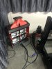
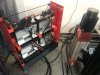
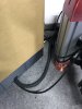
Thought I'd share some pics of the build so far. This will be publicly available via OnShape (or I can post a bunch of STL's). It's a mix of 3D printed parts, carbon fibre and some custom panels which I got done (will get done!) locally.

First, the final CAD idea:

Screen Shot 2020-01-12 at 10.03.52 PM.png
Screen Shot 2020-01-12 at 10.03.45 PM.png


The idea is to build a case that:
  1. Takes 240v direct
  2. Is switched, itself
  3. Remove 240v 30a relay.
    1. Has a remote, so I can leave it switched on, and press a remote from my seat to turn it on.
  4. Includes a FN2070 16a EMI filter
  5. 240-12v supply for the fans
  6. Includes mounting for the Arduino
  7. Includes 40mm polyester fibre accoustic insulation (I'm affected by the 10khz tone these things emit)
  8. Has sufficient airflow given (6)... that I'm covering everything up
  9. Stands against a wall and can be tied to that wall (I live in NZ, Earthquakes).
  10. Doesn't take up much floor footprint. My office is cluttered enough as it is.
There's prob more, but I forget :)

The case is built primarily out of pla. Some parts might be better done in PETG (clamps over carbon fibre scaffold, for example) so that they can flex a bit more. The idea is there.

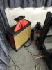
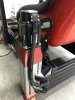
The design allows for the wrapping of accoustic material around the carbon frame all the way up. Lower and upper accoustic barriers are hangled by way of "fabric retainers", basically platforms that hold fabric. IT's hard to spot these in the drawing above.

Anyway; there's room for about 40mm of p.fibre around all AASD drivers, and that includes space for venting.

The lower base holds a 120mm fan directed intowards the case for +ve pressure. The fabric surround the drivers acts as a guide for this air, taking it past the heat fins of the AASD units. The extractor at the top is a 140mm fan.

I'm currently building/printing the unit. I'll post some more pics as I go!!!
 
Last edited:
Things are a little on hold at the moment while I source some braid shielding for the motor wires.

some history to this point:

I got it all "1st time configured" and ran into a couple of "noob design" problems:

1) EMI was a far, far larger problem than I thought. The arduino was shutting down once I got out of the pits. I did manage some laps at some point, but think it was fluke. This *could* also have been due to a large foot entering the arduino picture (see (2) below) earlier, I'm not sure. Massive single continuous tone heard in the Quake 'I am not a sub' sub. Nothing shielded at this point so not going to even bother trying to guess.

It *did* work, albeit breifly.

2) I munted my arduino input by stepping on it (while connected) during setup. This bent and disconnected the PCB mount socket from the board. I did fix it and have it going on the bench. My first setup sort of worked (or didn't), but then in my 2nd test setup I STEPPED ON IT AGAIN (face palm). This should *proabably* teach me something. Not sure what, but I feel a lesson in the air.


So I'm waiting on another arduino plus some copper braid.
Intention is to shield all the motor power wires.

I did some tests with a scope today. Saw 180mV holding the probe to the PVC shield of an unshielded power cable. This went down to about 10mV when shielded. (I have 5m of shielded 4 core that I'm using to test. Dont unfortunately have the other 8m I need to complete the other power cables).

So shielding is a promising thing..

I also took steps to build and test a "neil-o-cage", aka: faraday cage build over plastic. It's Dbl sided Alu Foil, Alu Foil (i.e: cooking type alu foil), another layer of dbl sided alu tape foil, then a last layer of alu-foil (cooking type). Only reason for the "cooking type" was a) I had it, and b) it stopped the dbl sided tape alu foil sticking to *everyting*

It turns out to make a large difference.

Probe on scope showed 180mV on unshielded. Inside the grounded neil-o-cage, shows either 10-20mv. My scope is cheap. Made of cheese most likely. Still, the test showed that the shield is doing SOMETHING with regad to the signals emitted by the motor power cables. I've got vid. Perhaps a post is in order!
 
Upvote 0
FYI: more EMI pictures here and here. Using a power line filter here. Effect of shielding here.

Aha! Nice. Thank you. I'm going to run the rears inside the extrusion. I've got one shielded power line (only bought 5m of the stuff at the time, should have got waaaaay more). The others will be braid over the top since that happens to be what Ive ordered...

I think it was the same tape that I used to create the cage. Thanks for sharing the results!
 
Upvote 0
It's been a while. I've been waiting on shielded cable for the motors, and also sliced up my hand pretty good. The later makes doing stuff (building things) kinda hard!

The cable has arrived. I need to cut it up, terminate it to the connectors, re-route my data vs power wiring, and then see where the project is at.
 
Upvote 0
I've "munted" / "munged" some holes in the back side of the power tray (the lower part of the case that holds the filter, power joiners, fan etc) to let data cables come out the back, AWAY from the power cabling which is routed out the front. Hmm. I should post some pics!
 
Upvote 0
IMG_6018.jpg

Large horribke hole in the bck of the case. I managed to split the center back piece/side in the process. Yay. Not.

I'm not overly worried. This is a test build, and I can re-print the center piece if I feel the need.
 
Last edited:
Upvote 0
IMG_6020.jpg


I completely rewired the data cables using shielded cat6. Yet to merge that shielding to 'somewhere'. You can see my naive arduino faraday cage in the background. I'll try to sensibly join the cable shields to that cage if I can.
 
Last edited:
Upvote 0
well, it's been a while, but I have an update! It's almost done.
The good:
  1. It does reduce noise; quite a bit actullay. I still hear some, but it's not as piercing as before.
  2. It's small! Everything is in there (EMI filter, drivers, arduino). One box next to the rig.
  3. Fans work great. It's super silent. You barely know its on. The 10khz noise (what's left) is louder than the fans.
The not-so-good:
  1. It's hard to work with. Being small there's little space. Next version I'll put in waaaaay more space, and make it possible to work on the power/distribution/arduino bits even if all drivers are installed.
  2. EMI is a real issue. 3D Printer parts work, but I'd choose sheet metal if I did it again
I think it'll need more than 40mm padding around the driver to shut them up. If I did it from sheet metal I'd make some panel inserts (somehow) that could be placed/attached onto the side panels. That way the core holds the drivers/electronics and the panels provide the accoustic damping.

I'll post a few pics
 
Upvote 0
Some pics! The case is 'brown' because I havn't taken the protective film off the acrylic panels yet.

Also interesting, I need to re-do the motor coverings. The cover needs to come down as far as possible. Noise is emitted well into the 3D printer motor mounts. It's not enough to cover JUST the motor. It's also emitted right out the top, so the covering must be good there as well.

Covers you see in the last shot are of course "testing" style, do you like my packing tape? :)
 

Attachments

  • IMG_6117.jpg
    IMG_6117.jpg
    567.2 KB · Views: 540
  • IMG_6122.jpg
    IMG_6122.jpg
    747.9 KB · Views: 500
  • IMG_6123.jpg
    IMG_6123.jpg
    574.6 KB · Views: 451
  • IMG_6124.jpg
    IMG_6124.jpg
    540.7 KB · Views: 412
  • IMG_6126.jpg
    IMG_6126.jpg
    487.1 KB · Views: 397
  • IMG_6127.jpg
    IMG_6127.jpg
    804.2 KB · Views: 407
Upvote 0
This is crazy, I've got all these wires laying around wild. USB - cables partly cross with the servo motor connectors, the power supply from my Fanatec DD is lying in the cable tangle. Also no power filter. But I have everything nicely grounded in a circle. No problems with EMI, also my HP-Reverb works fine. I wish you a lot of success with this project!
 
Upvote 0

Latest News

Back
Top